From CAD to the shop
Components I machined, 3D printed, and laser cut, alongside my own engineering drawing.
Harvard University
Overview
Selected coursework exploring assemblies, gear trains, bills of materials, and technical drawings. The work connects design intent to the dimensions, fits, and tolerances needed to make and assemble parts.
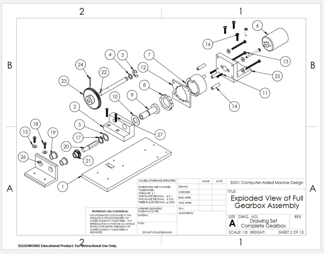
Gallery 01 is my own engineering drawing; 02 and 03 show the assembly and bill of materials. Drawings 04 through 09 document parts I manufactured. I modeled and 3D printed the motor mount and shaft support, machined the shafts and aluminum support, and laser cut the front plate. Each caption identifies my fabrication work.
Communicate the complete assembly
An exploded view and bill of materials show how individual components fit into the larger mechanism. Part drawings then communicate the geometry and manufacturing details needed at the workbench.
Gallery
My engineering drawing
My own drawing, with orthographic views and dimensions.
Assembly reference
Exploded view showing how the components fit together.
Assembly documentation
Bill of materials for the complete assembly.
Motor mount · CAD & 3D printing
I modeled this part in CAD and 3D printed it.
Round shaft · Machining
I manufactured this part using a lathe, vertical saw, and drill press.
Shaft support · CAD & 3D printing
I modeled this part in CAD and 3D printed it.
Aluminum support · Machining
I manufactured this part using a vertical band saw and drill press.
Hex shaft · Machining
I manufactured this part using a lathe and vertical saw.
Front plate · Laser cutting
I laser cut this part.
Keep exploring
Electricity-free diagnostics