LeBot James
A small starting box. Steep ramps. A robot built to keep scoring.
Harvard ES 51 · Computer-Aided Machine Design
- Final mass
- 4.87 lb
- Ramp climbed
- 30°
- Reliable scoring tier
- 14 in
- Drive & arm actuation
- 3 motors
Overview
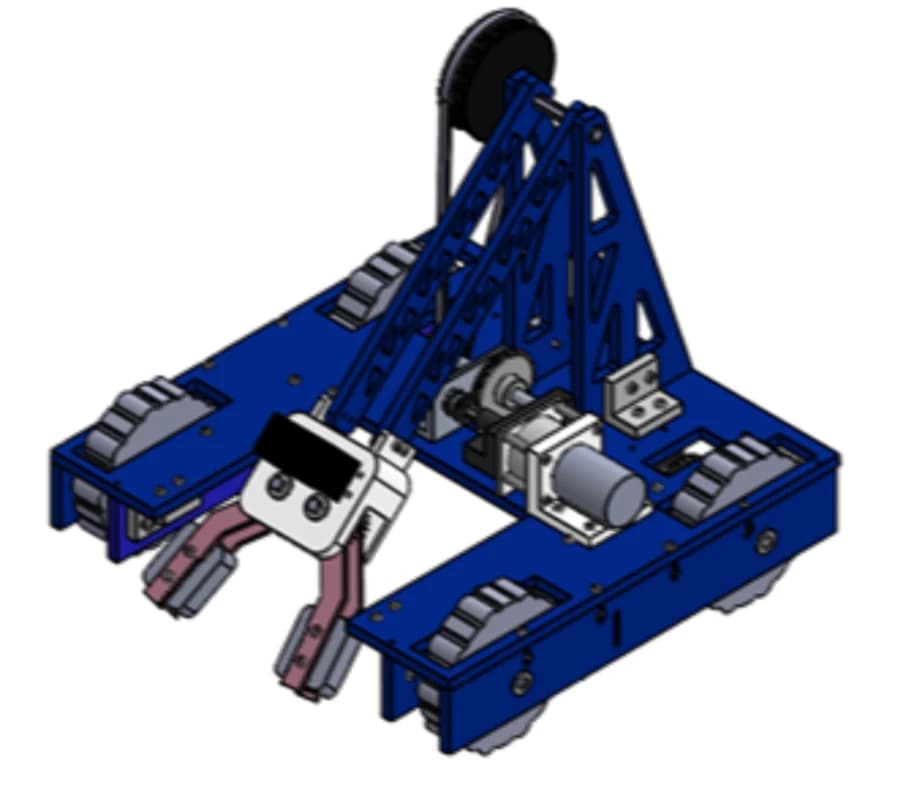
LeBot James was our five-person team’s answer to ES 51’s Turf Wars competition: start inside an 11 × 11 × 11-inch ‘Box of Justice,’ climb 15° and 30° ramps, and place tennis balls, blocks, and dog toys into elevated goals. The challenge was making those actions repeatable with a compact machine and only three drill motors.
On a five-person team, I contributed to concept development, engineering analysis, final specifications, and the bill of materials. I also helped fabricate components using a lathe, vertical band saw, drill press, CNC mill, and 3D printing.
01 / Make the tradeoff deliberately
We explored an elevator, a four-bar arm, and a powered intake before choosing a two-bar arm. Our weighted Pugh matrix favored the simpler mechanism: fewer joints, less friction, and less machining while still folding into the starting box. We focused on reliable scoring at 7 and 14 inches, accepting that we would not reach the 21-inch goal.
02 / Grip mattered as much as torque
Two drill motors drove the rear wheels through 3:1 spur reductions. Our analysis showed that traction, rather than motor torque, limited climbing on the 30° ramp. Cast Ecoflex 50 silicone wheels gave the robot grip on turf; physical tests confirmed repeated climbs without slipping. That connection between a calculation, a material choice, and the actual field was central to the design.
03 / Check the arm before building it
A third drill motor drove the arm through a 3:1 gear stage and an approximately 5:1 belt reduction, for about 15:1 overall. SolidWorks FEA of the acrylic arm under a 4.5 N end load predicted roughly 3 MPa maximum stress and 1.52 mm tip deflection. Alongside torque, reach, and center-of-mass calculations, this helped us check the mechanism before committing to fabrication.
04 / What it was like to operate
A scoring cycle began with the driver lining up the claw around an object and closing the servo gripper. The arm then lifted it toward the goal, and the driver opened the claw to release it. Predictable arm motion and steady traction made that sequence repeatable. In testing and competition, the robot climbed both ramps and scored in the 7-inch and 14-inch goals with objects of different shapes.
05 / What I would improve next
The report identified practical limits: belt friction slowed the arm, acrylic parts were vulnerable to impacts, and the claw struggled with unusually shaped objects. For another iteration, I would focus on reducing pivot friction, trying more compliant gripping surfaces, and lowering the batteries for stability. Reaching the highest goal would also mean revisiting how the arm folds into the starting box.
Gallery
LeBot James placing an object into an elevated competition goal
Completed robot showing the arm and fabricated chassis
Early top and side concept sketches of the robot
SolidWorks arm stress analysis, approximately 3 MPa maximum modeled stress
Center of mass & tipping analysis
The report estimates a tipping angle of about 40 degrees with the arm retracted, above the 30-degree competition ramp. Raising the arm reduces the stability margin.
Physical scoring test on the competition field
Keep exploring
Formula SAE