Two-Wheel Self-Balancing Robot
Building a lightweight robot with Paul. V2 is printed; next up are stronger motors and cleaner electronics packaging.
Ongoing · Second iteration assembled
Personal project with Paul Perez · Mechanical and electrical engineering
Overview
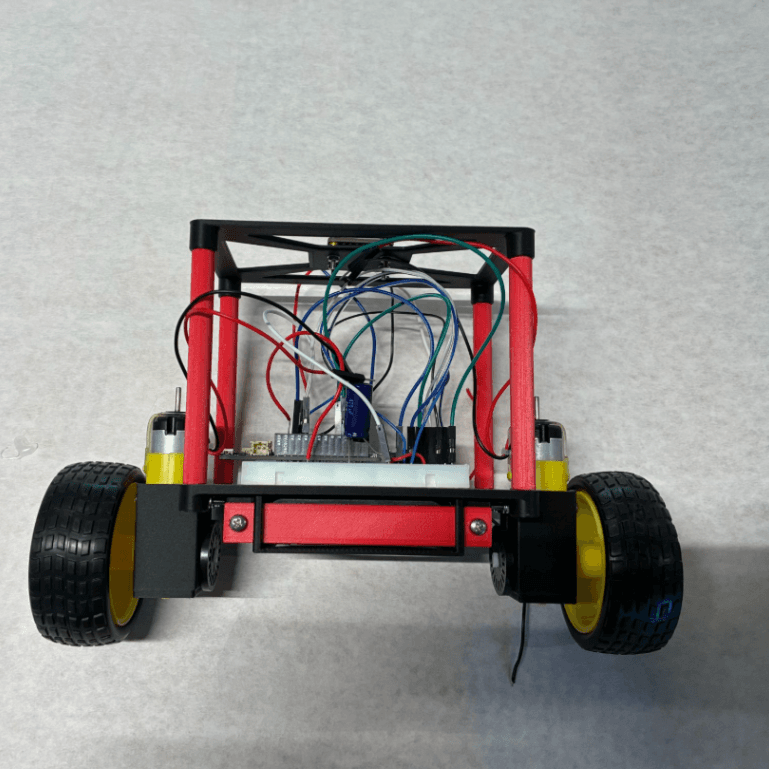
The second iteration is together.
- The problem
- Paul Perez and I are building a two-wheel balancing robot. Our small motors made weight important, but the first build showed me that saving material only helps if the parts still hold up.
- My contribution
- I handle the mechanical design and printed parts; Paul handles electronics and controls. I revised the thin battery holder, added a sliding pin, and tried horizontal printing for the rods. The V2 prints came out great, and the second iteration is together.
Build notes · October 27, 2026
- Built
- Second iteration assembled
- Confirmed
- Motor fit & hole alignment
- Latest update
- V2 prints completed
Prototype 01 · First build
Our first prototype. Paul and I are still working on getting it to balance, but this is where the printed parts, motors, and electronics came together.
Watch on YouTube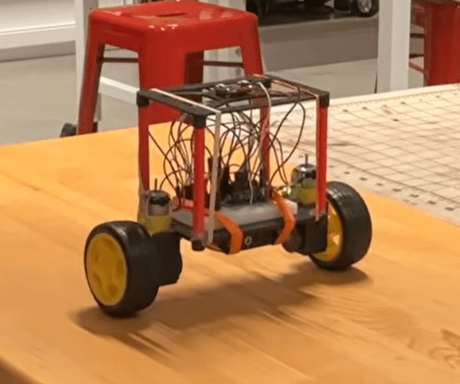
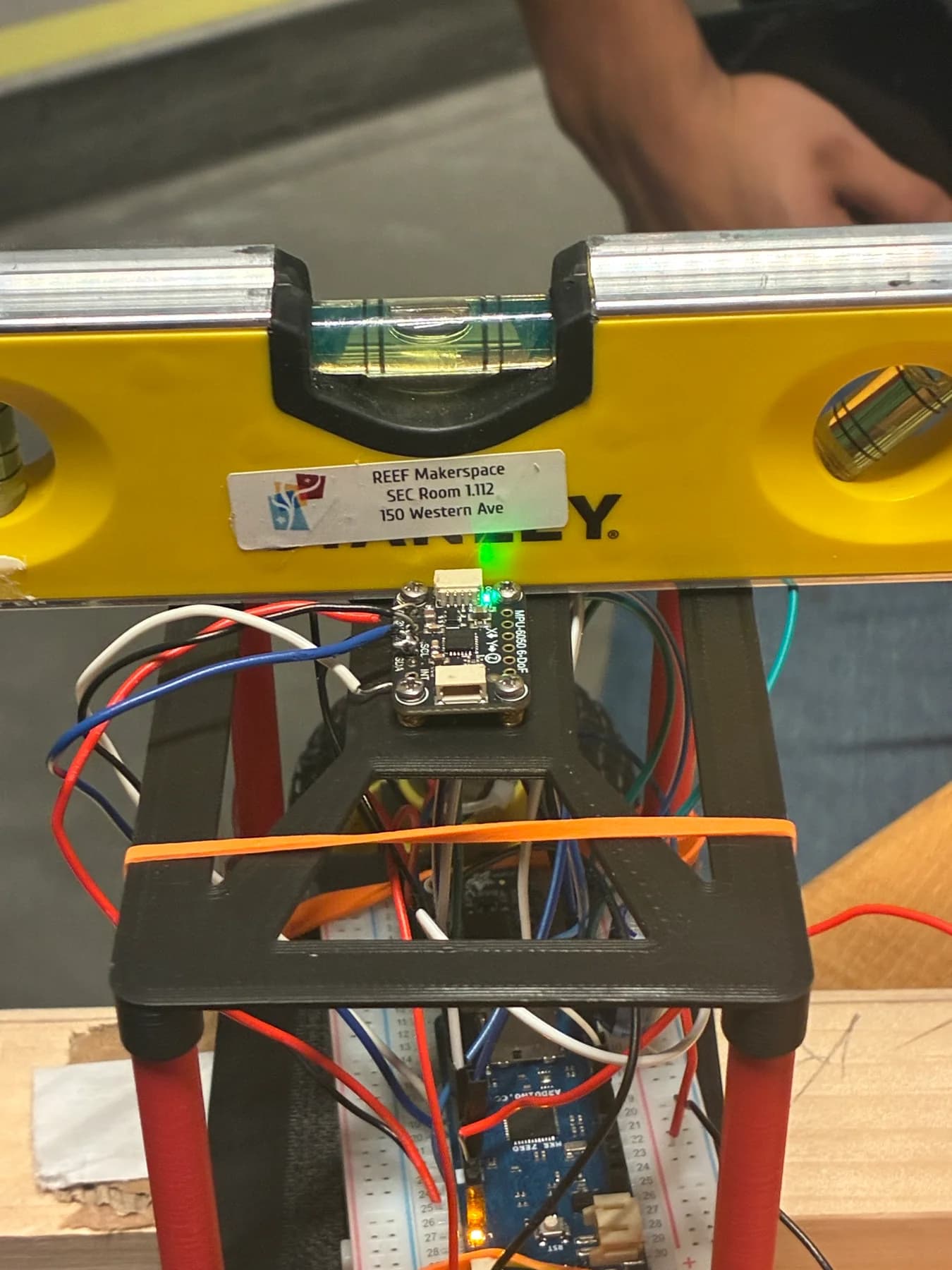
Why I designed it this way.
The main constraints were our motors, the parts we had, and how much time we could spend printing.
Keep the weight down
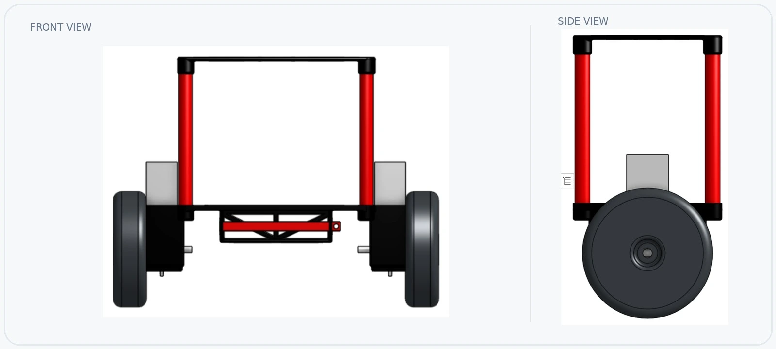
Our motors aren’t very strong, so weight mattered from the start. My first sketch had three plates: batteries, circuit board, and sensor. I cut that down to two by moving the batteries into a slot under the base. That also kept battery-mounting screws away from the circuit board. I added cutouts to the plates to save more weight.
Use what we could find
I considered buying wheels, then making my own with rubber bands for traction. We ended up finding spare wheels in the lab’s junk bin, which saved us that work. The motors’ built-in gearboxes made them awkward to package, so I placed them vertically and used nuts and bolts through their two mounting holes instead of relying on printed threads at the motor mounts.
Try printed connections
I wanted to keep the rods and their connections 3D printed. Since the top plate only carries a light load, I reduced the rods from 10 mm to 8 mm in diameter and used M5 threads. I started with a 0.15 mm offset between the male and female parts, planning to test a small hole-and-shaft sample before spending time and material on the full set.
Getting the first print to stick
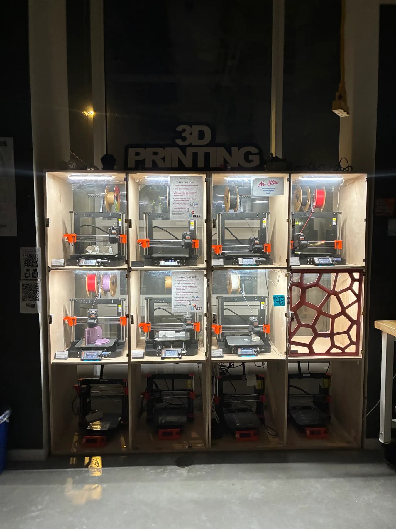
The preset settings weren’t working for the lower chassis. The PLA kept losing adhesion, so I slowed the print down and adjusted the supports. That got us through the first print, but it took roughly ten hours. It made testing small pieces first feel a lot more worthwhile.
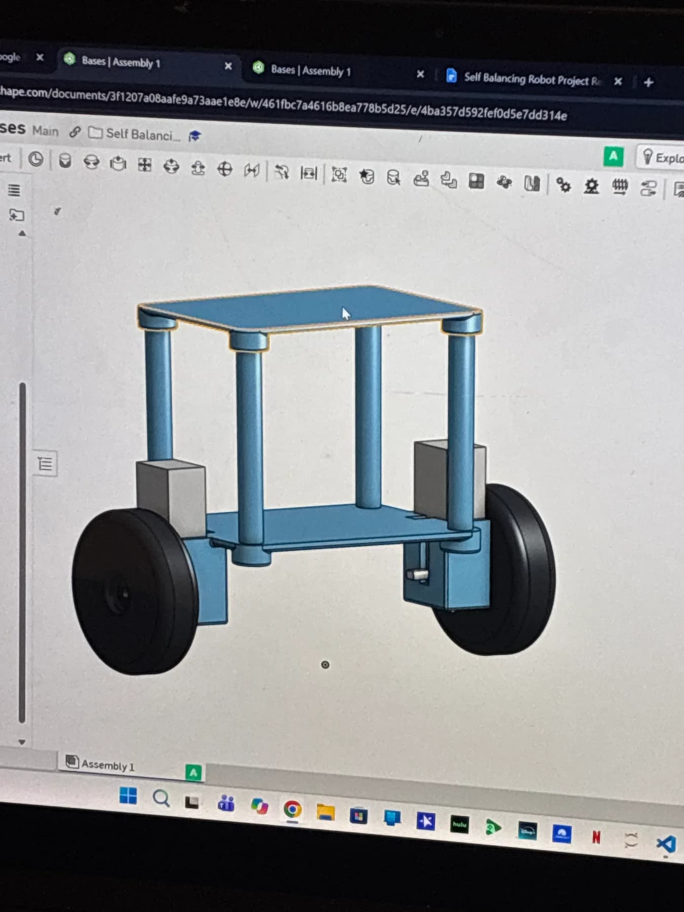
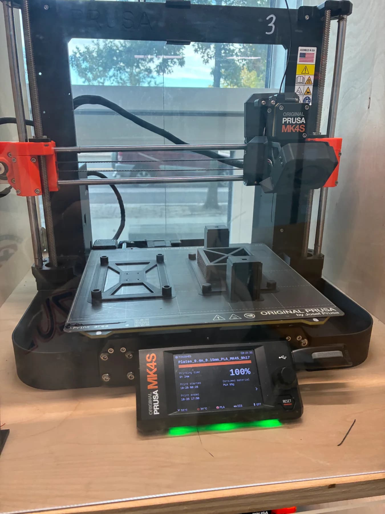
The motors fit the way I wanted.
I used the manufacturer’s dimensions for the motor mounts, and the holes lined up when we assembled them. The pockets were snug too. The top plate also worked well. That let me focus the V2 changes on the battery holder and rods. Stronger motors may mean revisiting the mounts in a later revision.
What broke, and what I changed.
Getting the parts to fit was one thing. Finding out whether they held up took the first build.
I made the slot too thin.
I got too greedy trying to save weight. The battery slot couldn’t support the pack and broke, so we took it off and temporarily attached the batteries another way. That let Paul keep testing without waiting for a whole new print.
The downside was that the batteries could move. Since that changes the weight distribution, I don’t want to keep tuning around a pack that shifts between attempts.
- What I changed
- I made the battery slot thicker and added a sliding pin that screws on and off, so the pack stays in place and the batteries are easy to take in and out.
- Result
- The V2 holder is done: it’s strong, easy to load and unload, and holds the pack in place.
Stronger rods, messier threads.
The rods were weak, especially at the threaded ends. I tried printing them upright and horizontally to compare strength with thread detail. The horizontal ones felt much more rigid and didn’t break as easily, so that’s the direction I’m going with.
The tradeoff was the thread. Printing horizontally left it slightly oval with some extra filament. I sanded that down, and it screwed in smoothly. The thread has less contact than I originally intended, but the fit worked in my test.
- My choice
- I’m accepting some sanding in exchange for rods that hold up better. For this prototype, that’s worth more to me than getting clean threads straight off the printer.
- What’s left
- Next I need to see how the full set holds up in the assembled frame. The comparison so far is from handling the rods and trying the fit.
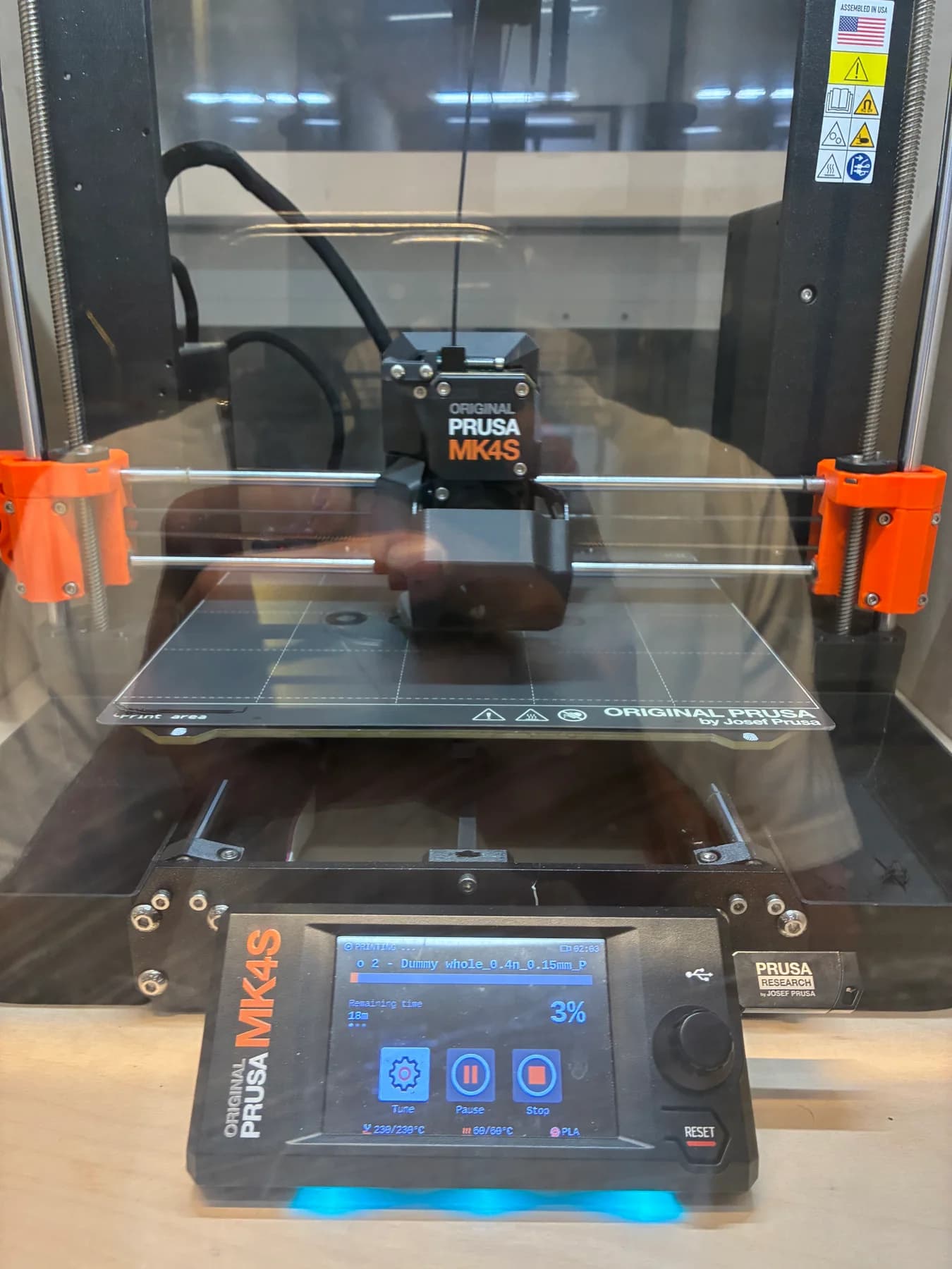
What I’m changing next.
With the V2 prints done, Paul and I are looking at the motors, electronics, and how everything fits inside the frame.
Find stronger motors
Our current motors have been a constraint from the start. For the next revision, we want to find stronger ones. I’ll need to revisit the mounts once we know what we’re using.
Give the circuit a proper enclosure
I want to CAD a housing for the breadboard so it has a proper place in the robot. We’re also considering moving from a breadboard to a perfboard, so I want to settle that before designing around it.
Look into a different microcontroller
Paul mentioned getting a better microcontroller. We haven’t picked one yet; that’s something we’ll work through together before I finalize the electronics housing.
Make room for the wires
I want to make a housing for the wiring too. Right now the wires run through the open frame, and I’d like the next revision to keep them organized while still letting us get in and work on the electronics.
Saving weight only helps if the part still does its job. The motor mounts fit, the battery holder was too thin, and changing how I printed the rods helped more than chasing perfect threads. Those are the things I’m taking into the next build.
Results & validation
We have an assembled second iteration with the electronics mounted. We haven’t tested the electronics or balancing yet.
Lessons & next steps
We’re looking for stronger motors, considering a perfboard and a different microcontroller, and planning housings for the circuit and wires. I want the next revision to be easier to work on as well as cleaner to assemble.